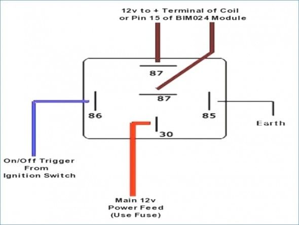
5 Pin Relay Wiring Diagram For Fan

How a 5 pin relay works.
5 pin relay wiring diagram for fan. The book includes a large amount of sensible tips for different. Diy relay easy step by step electrical wiring fan example how to wire a relay how to wire a fan how to wire fog lamp how to wire a fuel pump relay variou. Find a spot to secure the relay with a screw or a bolt. Relay 5 pin wiring diagram duration.
Chris craft 307 867 views. Locate the relay in immediate proximity to the fan being used. That s why i m trying to fiddle with the wires that leave the relay not the relay itself. Wiring diagram includes numerous comprehensive illustrations that show the relationship of varied things.
I have attached the electrical wiring diagram from the turn indicator i believe what you will discover is that the turn signal and hazard the 8 pin flasher relay toyota is using here is kinda alien to me. 5 pin wire diagram pin rocker switch wiring diagram image wiring for 5 post relay wiring diagram by admin from the thousand images on the internet concerning 5 post relay wiring diagram we selects the best series with greatest quality simply for you and this images is usually one of pictures choices in our finest photographs gallery concerning 5 post relay wiring diagram. Auto electric cooling fan wiring how to diy duration. It contains directions and diagrams for different varieties of wiring strategies and other things like lights windows and so on.
Bosch 5 pin relay wiring diagram wiring diagram is a simplified satisfactory pictorial representation of an electrical circuit it shows the components of the circuit as simplified shapes and the power and signal connections amid the devices. Remove the nut on the battery terminal and put the wire connector over the bolt and tighten the nut. Electric fan relay wiring diagram wiring diagram is a simplified tolerable pictorial representation of an electrical circuit it shows the components of the circuit as simplified shapes and the capability and signal contacts between the devices. Install a 10 gauge wire to the battery positive terminal with the use of a round electrical connector.


